Most best option This means purchasing and using a high-quality power supply. But if there is no opportunity and/or there is a desire to improve the unit you already have, then good results can be obtained by modifying a cheap (budget) power supply.
Chinese designers, as a rule, make printed circuit boards according to the criterion of maximum versatility, that is, in such a way that, depending on the number of installed elements, quality and, accordingly, price can be varied.
Therefore, if you install those parts that the manufacturer saved on and change a few other things, you will get a unit in the middle price category. Of course, it cannot be compared with expensive copies, where the topology of printed circuit boards, circuit design, and all the details were initially calculated to obtain high quality.
Whatever you do with your power supply, you do at your own peril and risk!
If you do not have sufficient qualifications, then do not read what is written here, much less do anything!
But for the average computer this is a completely acceptable option.
First of all, you need to open the power supply and estimate the size of the largest transformer; if it has a tag with the numbers 33 or higher at the beginning and has dimensions of 3x3x3 cm or more, it makes sense to tinker. Otherwise, you are unlikely to achieve an acceptable result. 

In photo 1 there is a transformer of a normal power supply, in photo 2 there is a transformer from a frank Chinese.
You should also pay attention to the dimensions of the group stabilization choke. How larger sizes transformer and inductor cores, the greater the margin for saturation currents.
For a transformer, getting into saturation is fraught with a sharp drop in efficiency and the likelihood of failure of high-voltage switches, for a choke - a strong voltage spread in the main channels.

Rice. 1 Typical Chinese ATX power supply, no mains filter.
The most critical details in a power supply are:
.High voltage capacitors
.High voltage transistors
.High voltage rectifier diodes
.High frequency power transformer
.Low-voltage diode rectifier assemblies
Revision:
1. First, you need to replace the input electrolytic capacitors; replace them with capacitors of larger capacity that can fit on the seats. Typically, cheap units are rated at 220µF x 200V or at best 330µF x 200V. We change it to 470µF x 200V or better to 680µF x 200V. These capacitors affect the ability of the unit to withstand a short-term loss of mains voltage and the power supplied by the Power Supply.


Rice. 2 Input electrolytic capacitors and high-voltage part of the power supply, including a rectifier, half-bridge inverter, electrolytes at 200V (330µF, 85 degrees).


Next, you need to install all the chokes in the low-voltage part of the power supply and the line filter choke (the place for its installation).
The chokes can be wound yourself on a ferrite ring with a diameter of 1-1.5 cm using copper wire with varnish insulation with a cross-section of 1.0-2.0 mm, 10-15 turns. You can also take chokes from a faulty power supply. You also need to solder smoothing capacitors into empty spaces in the low-voltage part. The capacitor capacity should be selected as maximum as possible, but so that it can fit in its standard place.
Usually it is enough to put 2200µF capacitors at 16V series Low ESR 105 degrees, in the +3.3V, +5V, +12V circuit.
In the rectifier modules of the secondary rectifiers, we replace all diodes with more powerful ones.
Power consumption of computers lately, increased to a greater extent along the + 12V bus ( motherboards and processors), so first of all you need to pay attention to this module.

Typical type of rectifier diodes:
1. - Diode assembly MBR3045PT (30A) - Installed in expensive power supplies;
2. - diode assembly UG18DCT (18A) - less reliable;
3. - diodes instead of assembly (5A) - the most unreliable option, subject to mandatory replacement.
Channel +5V Stby- We change the standby diode FR302 to 1N5822. We also install the missing filter choke there, and increase the first filter capacitor to 1000μF.
Channel +3.3V- we change the S10C45 assembly to 20C40 (20A/40V), to the existing capacity 2200uF/10V, add another 2200uF/16V and the missing inductor. If the +3.3V channel is implemented on a field device, then install a transistor with a power of at least 40A/50V (IRFZ48N).
Channel +5V- We change the diode assembly S16C45 to 30C40S. Instead of one electrolyte 1000uF/10V, we set 3300uF/10V + 1500uF/16V.
Channel +12V- We replace the F12C20 diode assembly with two in parallel UG18DCT (18A/200V) or F16C20 (16A/200V). Instead of one 1000uF/16V capacitor, we put 2 pieces 2200μF/16V.
Channel -12V- Instead of 470μF/16V, set it to 1000μF/16V.
So, we install 2 or 3 diode assemblies MOSPEC S30D40 (the number after D is the voltage - the more, the calmer we are) or F12C20C - 200V and similar in characteristics, 3 capacitors 2200 μF x 16 volts, 2 capacitors 470 μF x 200V. Electrolytes, install only low-impedance ones from the 105 degree series! - 105*C.

Rice. 3 Low-voltage part of the power supply. Rectifiers, electrolytic capacitors and chokes, some missing.
If the power supply radiators are made in the form of plates with cut petals, we bend these petals in different directions to maximize their efficiency.

Rice. 5 ATX power supply with modified cooling radiators.
Further refinement of the power supply boils down to the following... As is known in the power supply, the +5 volt and +12 volt channels are stabilized and controlled simultaneously. With +5 volts set, the actual voltage on channel +12 is 12.5 volts. If the computer has a heavy load on channel +5 (AMD-based system), then the voltage drops to 4.8 volts, while the voltage on channel +12 becomes equal to 13 volts. In the case of a Pentium-based system, the +12 volt channel is more heavily loaded and the opposite happens. Due to the fact that the +5 volt channel in the power supply is made of much higher quality, even a cheap unit will power an AMD-based system without any problems. Whereas the power consumption of the Pentium is much higher (especially at +12 volts) and the cheap power supply must be improved.
Excessive voltage on the 12 volt channel is very harmful for hard drives. Basically, HDD heating occurs due to increased voltage (more than 12.6 volts). In order to reduce the voltage of 13 volts, it is enough to solder a powerful diode, for example KD213, into the gap of the yellow wire powering the HDD. As a result, the voltage will decrease by 0.6 volts and will be 11.6 - 12.4V, which is quite safe for the hard drive.
As a result, by upgrading a cheap ATX power supply in this way, you can get a good power supply for a home computer, which will also heat up much less.
Greetings to all readers. Been asking to test this for a long time pulse source food, which has become very popular among DIYers. This is a fairly cheap unit that can be used as a power source in a homemade soldering station, laboratory power supply, etc., in general, a universal thing.


The Chinese produce several versions, the circuit design is almost the same, the only difference is in the output voltage and current, my sample is 24 Volts, with a stated current of 4A and 6A if an additional cooler is used.
The board is quite compact, the overall dimensions with a small error you now see on your screens.

About the scheme. This is a single-cycle network step-down switching power supply with output voltage stabilization and current protection. The circuit was built on the basis of the not very popular CR6842 PWM controller (analogous to SG6842), for me, on the UC38XX family of microcircuits the unit would be more repairable, the original microcircuit is quite expensive.
The board is double-sided, the components are sealed well.


An example power supply circuit is shown below.
The power input is made in an interesting way, essentially these are clamps where the network wires are inserted; there is no need to solder or screw in anything.
Next comes the fuse and surge protector, everything is as it should be.
The diode bridge is a ready-made assembly KBP307 (3A, 700V).
After the bridge we see a thermistor, its initial resistance is 5 Ohms at a maximum current of 3A, it is designed to reduce the starting current when the unit is connected to a 220 Volt network.
A smoothing electrolyte with a capacity of 82 μF, taking into account 1 μF per 1 watt of power, everything is as it should be.
Then everything is clear - a generator microcircuit, a power N-channel field switch, in this version there is a P20NK60 transistor, judging by the marking 20 Amperes 600 Volts, it has a colossal current reserve, installed on a small radiator.

Pulses are supplied to the gate of the field-effect transistor through a limiting resistor and a diode, which is switched in the reverse direction and is designed to quickly discharge the gate capacitance of the field-effect transistor.
In the output part there is a half-wave rectifier based on a dual Schottky diode in a TO-220 package, moreover, both diodes are connected in parallel, which significantly reduces the transition resistance, and therefore heating.
After the rectifier, there is a filter, which consists of two electrolytes and a choke, moreover, one electrolyte is placed before the choke, the second after.
Well, there is an LED with a limiting resistor, which indicates the presence of output voltage.

The output voltage is controlled by an optocoupler, and the voltage is set by an adjustable zener diode TL431. By changing the ratio of the resistances of the resistive divider in the zener diode circuit, you can change the output voltage of the power supply within small limits.


In general, everything suggests that the power source is good, but we’ll still check it.
The first test is to check the output voltage.
Everything is fine, and the no-load current is only 12-13mA! which is a very good indicator.

The declared output current is 4A.
According to Uncle Ohm's law, in order to remove 4 amperes of current from a 24 Volt source, we need a load with a resistance of about 6 Ohms, you can use a nichrome spiral, but I had a 20-watt 5.6 Ohm resistor lying next to me, so I connected it.

The source is connected via a network wattmeter; a low-voltage Volt/Ampere/Watt meter is used as a meter at the output.

At a current of 4.2A, the output voltage drops slightly.
With this situation, the unit consumes about 110 watts from a 220 Volt network, and the output is about 100 watts, the efficiency is around 90%, which is very good.
I tried to remove the current at 5.5A, everything was also fine, when I tried to remove more, the protection was triggered.
By the way! The protection is implemented on the hiccup principle and works well.
When a short circuit occurs, a voltage drop occurs across the current sensor, which is a low-resistance resistor connected to the source circuit of the field switch. The microcircuit monitors the fall and when too great importance goes into defense.
I also took some measurements of the output voltage ripple.
Idling, division 20mV

Current 0.6A, division 20mV

Current 3.6 A division 20 mV

Current 4.2A division 20mV

The results were amazing, I thought there would be more pulsations.
At the end I left the unit working for 10 minutes, output current 3.6A
After 10 minutes, without turning off the unit, I took temperature measurements
1) On the radiator of the diode rectifier
2) On the radiator of the field key
3) Transformer windings
4) Transformer core
5) On the input diode rectifier
Advantages.
1) Compact, lightweight, well made.
2) Price, well, so-so, not too cheap and not expensive
3) Versatile
4) Excellent stabilization
5) Availability of short-circuit protection, fulfills its purpose
6) The presence of a filter both at the input and at the output; in general, the circuit is well organized.
Flaws
1) It is better to change the radiators or screw on the cooler; during long-term operation at high currents they get very hot.
2) A small-sized transformer, seemingly no power reserve, so at high currents it will overheat.
Results.
Everyone knows that the Chinese save on everything, and this power source is no exception. But taking into account its advantages, I recommend it, it is not afraid of short circuits, it is made well, the components are sealed neatly, there is protection, good stabilization, in general, everything that is needed for, say, implementation in a homemade soldering station or a simple laboratory power source, there are a lot of areas of application.

The product can be purchased
A detailed video of the test can be viewed below.
Sincerely - AKA KASYAN
MY YOUTUBE CHANNEL
Lithium-Ion (Li-Io), charge voltage of one can: 4.2 - 4.25V. Further by the number of cells: 4.2, 8.4, 12.6, 16.8.... Charge current: for ordinary batteries is equal to 0.5 of the capacity in amperes or less. High-current ones can be safely charged with a current equal to the capacity in amperes (high-current 2800 mAh, charge 2.8 A or less).
Lithium polymer (Li-Po), charge voltage per can: 4.2V. Further by the number of cells: 4.2, 8.4, 12.6, 16.8.... Charge current: for ordinary batteries is equal to the capacity in amperes (battery 3300 mAh, charge 3.3 A or less).
Nickel-metal hydride (NiMH), charge voltage per can: 1.4 - 1.5V. Further by the number of cells: 2.8, 4.2, 5.6, 7, 8.4, 9.8, 11.2, 12.6... Charge current: 0.1-0.3 capacity in amperes (battery 2700 mAh, charge 0.27 A or less). Charging takes no more than 15-16 hours.
Lead Acid, charge voltage per can: 2.3V. Further by number of cells: 4.6, 6.9, 9.2, 11.5, 13.8 (automotive). Charge current: 0.1-0.3 capacity in amperes (battery 80 Ah, charge 16A or less).
Today, ready-made switching voltage stabilizer modules based on the LM2596 chip have become available.
Quite high parameters are declared, and the cost of the finished module is less than the cost of the parts included in it. The small size of the board is attractive.
I decided to purchase a few and test them out. I hope my experience will be useful to less experienced radio amateurs.
I bought modules on ebay, as in the photo above. Although the site showed 50V solid capacitors, the auction lived up to its name. The capacitors are ordinary, and half of the modules have capacitors for a voltage of 16 V.
...it can hardly be called a stabilizer...
You might think that it is enough to take a transformer, a diode bridge, connect a module to them, and we have a stabilizer with an output voltage of 3...30 V and a current of up to 2 A (short-term up to 3 A).I did just that. Without load everything was fine. A transformer with two windings of 18 V and a promised current of up to 1.5 A (the wire was clearly too thin by eye, and so it turned out).
I needed a +-18 V stabilizer and I set the required voltage.
With a 12 Ohm load the current is 1.5 A, here is the waveform, 5 V/cell vertical.
It can hardly be called a stabilizer.
The reason is simple and clear: the capacitor on the board is 200 uF, it serves only for normal operation DC-DC converter. When voltage is applied to the input from laboratory block food, everything was fine. The solution is obvious: you need to power the stabilizer from a source with low ripples, i.e. add a capacitance after the bridge.
Here is the voltage with a load of 1.5 A at the input of the module without an additional capacitor.

With an additional 4700 uF capacitor at the input, the output ripple decreased sharply, but at 1.5 A it was still noticeable. When reducing the output voltage to 16V, the ideal straight line (2V/cell).

The voltage drop across the DC-DC module must be at least 2...2.5 V.
Now you can watch the ripples at the output of the pulse converter.

Small pulsations with a frequency of 100 Hz modulated with a frequency of several tens of kHz are visible. The Datasheet on the 2596 recommends an additional LC filter on the output. That's what we'll do. As a core, I used a cylindrical core from a faulty computer power supply and wound the winding in two layers with 0.8 mm wire.

The board shows in red the place for installing a jumper - the common wire of two channels; the arrow shows the place for soldering the common wire, if you do not use terminals.
Let's see what happened to the HF pulsations.

They are no longer there. Small pulsations with a frequency of 100 Hz remained.
Not perfect, but not bad.
I note that as the output voltage increases, the inductor in the module begins to rattle and RF interference at the output sharply increases; as soon as the voltage is slightly reduced (all this with a load of 12 ohms), the interference and noise completely disappear.
To mount the module, I used homemade “stands” made of tinned wire with a diameter of 1 mm.

This ensured convenient installation and cooling of the modules. The posts can get very hot when soldering and will not move like simple pins. The same design is convenient if you need to solder external wires to the board - good rigidity and contact.
The board makes it easy to replace the DC-DC module if necessary.
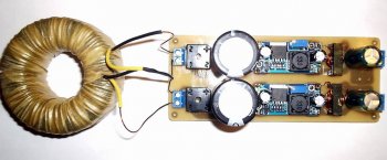
General view of the board with chokes from halves of some kind of ferrite core (inductance is not critical).
Final circuit diagram:
The scheme is simple and obvious.With a long-term load of 1 A current, the parts heat up noticeably: the diode bridge, the microcircuit, the module choke, most of all the choke (additional chokes are cold). Heating to the touch is 50 degrees.
When operating from a laboratory power supply, heating at currents of 1.5 and 2 A is tolerable for several minutes. For long-term operation with high currents, a heat sink to the microcircuit and a larger inductor is desirable.
Despite the tiny dimensions of the DC-DC module, the overall dimensions of the board were comparable to the analog stabilizer board.

Conclusions:
1. A transformer with a high-current secondary winding or with a voltage reserve is required; in this case, the load current may exceed the current of the transformer winding.2. At currents of the order of 2 A or more, a small heat sink to the diode bridge and the 2596 microcircuit is desirable.
3. It is desirable to have a large capacity power capacitor, this has a beneficial effect on the operation of the stabilizer. Even a large and high-quality container heats up a little, therefore a low ESR is desirable.
4. To suppress ripple with the conversion frequency, an LC filter at the output is required.
5. This stabilizer has a clear advantage over a conventional compensation one in that it can operate in a wide range of output voltages; at low voltages, it is possible to obtain an output current greater than what the transformer can provide.
6. The modules allow you to make a power supply with good parameters simply and quickly, bypassing the pitfalls of making boards for pulse devices, that is, they are good for beginner radio amateurs.